Further development of JFLEX:
Good, made even better
With JFLEX Hennecke has successfully expanded their continuous slabstock plant product family and at the same time bridged the gap between discontinuous and continuous slabstock plants. JFLEX offers users with medium-sized production volumes all the advantages of a continuous production process. Since its introduction at the K trade fair 2013 Hennecke was able to place the JFLEX very successfully within the market. The current generation now benefits from various improvements that have been gradually integrated in the context of expanded market requirements.
The positive reactions of slabstock processors around the world have shown that Hennecke has scored a hit with the new JFLEX. So far, the market gap lying between discontinuous and continuous slabstock lines has not yet been covered. The target groups of JFLEX are foam manufacturers who want to achieve a better quality and higher raw-material yield than is possible with discontinuous plants, but are unwilling to make the high investment in conventional continuous lines. JFLEX offers companies with medium-sized production volumes all the advantages of a continuous production process.
JFLEX lines are operated at one-fifth of the usual production speed of traditional continuous plants and still manufacture similar block sizes. Thus, the machine is only approx. twelve metres long. This extremely compact design provides a significant advantage over conventional slabstock plants, which measure up to 50 metres, making them more than four times as long. Due to the small space requirement, the user saves precious production space or can significantly reduce building costs. Hennecke enables this difference in length with a new liquid-laydown technology. For conventional, continuously operating slabstock lines, the expansion speed of the polyurethane mix determines the production speed. Typically, this is about five metres per minute. The specified speed also determines the length of the entire plant, as the foam must mature within a defined period of time before it can be cut.
The PU specialists at Hennecke have developed a method – patent pending – by which it is possible to operate with a production speed of one metre per minute, and thus to shorten the plant length accordingly. The main component of the new technology is the JFLEX retaining and rising zone: the so-called J-PIPE. Here, the liquid polyurethane mixture is poured on one side using a dispensing system. The expanding polyurethane foam exits on the other side without being able to press back into the liquid and thus expands along a rising plate. The system hereby takes advantage of the density difference between the reactive fluid on one side and the lighter foam on the other side.

This JFLEX process has been further optimised by Hennecke specialists using the experience gained in everyday production. With the further developed "Multiple Nozzle System", various foaming widths in the range of 1000 to 2300 millimetres can now be implemented very flexibly. The raw material distribution can be influenced by the user considerably better than before through the diameter of the dispensing nozzles and the distance and positioning of the multiple nozzle system from the paper. It is thus ensured that the mixture has the same age at every location over the entire width distribution. Meanwhile the multiple nozzle system of the JFLEX also demonstrates its capabilities in further PU applications, in which a uniform rising profile of the foam is the focus.
The second optimisation of the JFLEX process occurred in the area of the rising plate. By dividing into three segments instead of a single rigid element, the geometry can be better adjusted to the foam curve. Additionally, this geometry can now be adjusted motorised during the foaming process. Automatic adjustment is also possible via the control system of the plant depending on the formulation.
But Hennecke has perfected the plant not only with regard to the JFLEX process. It has also optimised the operation and the technical design of the flat top device.
The raw material efficiency is further increased through improved block geometry. The skins of the block are very thin and thus help to minimise the cutting loss. Hennecke technicians also scrutinised the setup times and were able to reduce them further. For example, the side paper is no longer removed after production, it instead remains in the tunnel and is thus ready for the next production. It has also been shown that during production with JFLEX the finished foam exits the tunnel after just seven metres of production and can then be immediately examined by the operator. Necessary formulation adjustments can therefore be achieved without any notable material losses. Conventional systems produce more than 20 metres within this period of time.
With these optimisations and new experiences, JFLEX is further matured and can be deployed reliably in slabstock production. Thus, the new plant type fits seamlessly into the Hennecke QFM and MULTIFLEX slabstock lines. As market leaders in the field of slabstock production, the tried and tested plants enjoy an excellent reputation worldwide.
Typical JFLEX production range
- Standard foam with a density of 15 to 45 kg/m³
- Use of fillers of up to 50 parts to 100 parts polyol and
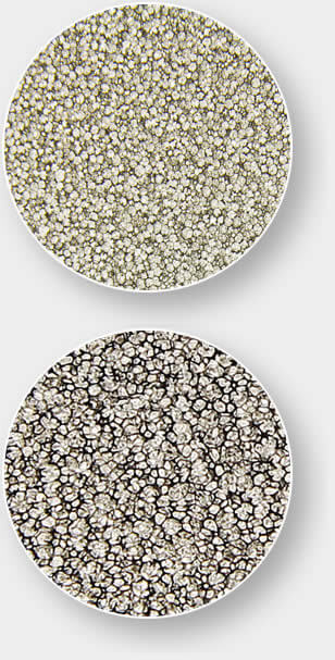
- Possible cell sizes from approx. 25 up to 50 ppi
An even finer cell structure can be achieved through an additional high pressure gassing of isocyanate with nitrogen. Likewise an even coarser cell structure is possible through degassing of isocyanate.
- Viscoelastic foam, MDI-based and with a density of 50 to 100 kg/m³
- HR foam with a density of 25 to 50 kg/m³
Examples of density and hardness distribution
Typical density distribution
(standard foam without fillers, 22 kg/m³)
Typical hardness distribution
(40% compression set)

In kg/m3

In kPa
")